Teacher information
Purpose
The purpose of this lab is to allow students to exercise their imagination within a complex mechanical problem. All of the skills and information they need to solve this problem they already have. As they look at the world around them, they have already observed, pondered, and investigated the way things work. Get the students to remember the experiences they have had to this point in their life playing with toys, using tools and testing new things and way to use them. All of us have wondered what makes something work, or why does an items do a job in a certain way. Students are now to take that wondering and put it to use, try out new materials, and methods of using a piece if equipment, experiment and see what you come up with. Students must be encouraged to try and fail and to try again.
The Problem
To build a spec. vehicle that will climb the steepest incline possible. The incline being a 6 ft. long by 2 ft. wide board covered with 60 grit sandpaper
The Rules
1) The frame of the vehicle must fit within these dimensions.
2) One motor only can be used to drive the vehicle. The motor is a specific type as listed below
3) Maximum total voltage allowable is 9 volts. Amperage is open, but use caution, to much amperage will burn up the motor when under load.
4) The vehicle may not be connected to any external device while under testing.
5) The vehicle must travel a minimum of twice it's own length. Climbing the full length of the incline at the maximum angle the machine can climb will gain you an extra 5% mark.
6) Remote controlling of the vehicle is prohibited.
7) Weight, traction device, layout, drive system etc. is open to whatever the design may be. The heavier it is the harder it is to climb, the faster it is the less climbing power it has. Center of gravity at maximum climb angle should be given careful consideration.
The Process of the lab
• The concept of brainstorming must be followed in detail for this lab. Students tend to grab the first idea that comes to mind and spend all their time working on that one idea when it may be an impractical one that will be to difficult to do.
• The problem solving flow chart should be handed out at the point that critical thinking and evaluation is discussed. Following the flow chart will give the students an path to follow in solving problems, redesigning, etc.
•Each section of the journal should be completed in their order, this will allow the students to follow a process that in the end will help them organize the process of their lab.
•Once a week the journals should be handed in for marking and making sure the proper process is being followed. Not following the process will lead to major problems for some students. Some will get totally lost and lose interest in the lab, others will get confused and frustrated because they have not followed the process as outlined.
•Set definite dates for specific events. Like journal due dates, testing dates and final due date!
Materials
Since there will be a wide variety of designs developed, the materials will vary according to what the students need. The teacher needs to have a wide variety if materials, fasteners, adhesives etc. on hand. The good news is that most of the materials can be donated to the project from various sources. Here is a list of sources that have been useful to the author for many years.
•Photocopiers- Most copier companies throw out old models and will give them to the school for the project. These machines contain a wealth of gears, chains, pulleys etc.
•Plastics- Local plastic shops have scrap bins if materials for the taking.
•Wood- Wood shop short ends, cabinet shops, building suppliers etc.
•Toys- Students usually have a lot of these sitting dead about the house.
•Metal- Copper coated welding rod works great. Short ends from the metal shop.
•Styrofoam- Broken boards from a building supply company.
MOTOR SPECS.
3.5 volt model motor. Approx. 20 mm dia, 50 mm in length, 1.5mm shaft RPM = 17000,Torque = 7 gr.
An example of the possible power that could be produced, is to have a speed reduction system that allowed the motor to run at 17000 rpm and the wheels turn at 100 rpm. 17000 ÷ 100 x 7gr = 1190 gr. of torque, or 1.19 kg of torque.
Traction devices:
•Wheels: Foam rubber, O-rings, solid
rubber. Styrofoam SM™
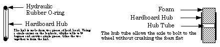
A hub of some kind must be fashioned for the O-ring or foam wheels.
RC vehicle wheels are not good for this project!
•Tracks: Model tank tracks, small V-belts, rubber inner-tube,
etc., etc.
•Walking legs: Same principle as a wheel but using sharp spiked
ends in the legs.
Drive Devices
•Gear and Chains: The best place to
find these are old photocopiers. May businesses which sell them just
throw out the old ones. Old ones have lots of gears and chains, the
newer style do not. VCRs and other like machines have small gears,
pulleys, belts etc.
•Belts and Pulleys: Pulleys are made in the same manner as the
O-ring hub as shown above. These can be made from two inches diam. to
what ever size you want. O-rings can be purchased at any hydraulic
shop.
•Elastic bands will work but the bottom of the pulley must be
flat and not in a V shape. Use three pieces of hardboard with the
center one 2- 3 mm smaller in diameter then the two outer
ones.
Frame:
The frame can be made from wood, sheet metal, aluminum copper coated welding rod or plastic. Have the frame as light as possible and as strong as possible, you will have to find the proper balance. If it is to heavy it won't climb. If it is not strong enough it will flex and lift the drive system (wheels) off the wall.
Helpful Hints:
a) Keep the battery and any additional weight as far below the axle and as far forward as possible.
b) A ground speed of less than four meters per min. is best.
c) The larger the wheel dia. the lower the weight can be mounted and the bigger the foot print of the wheel.
d) Allow the motor to run at max RPM under full load.
e) Don't use a 9 volt transistor radio battery, not enough amps.
f) Use bearings or bushings on all moving shafts. Cut friction as much as possible.
Calculating power increase and ground speed
One of the first things you will need to know is how to calculate the circumference of a circle. The circle can be a gear or pulley.
Circumference 2x pi x r
pi= 3.14 r= the radius of the circle. The radius is the distance from
the center of a circle to the outside edge.
An example: A circle 10 cm in diameter. The radius will be 5cm
The equation will look like this. 2 x 3.14 x 5= 31.4 cm in circumference.
If the pulley on the motor is 5 mm in dia., the cir. of that pulley will be 15.7mm....2 x 3.14 x 2.5= 15.7mm
To find the speed reduction and thus the power increase for a given pulley ratio follow these steps in the following example.
1) Drive pulley A cir..= 15.7 mm (2 x 3.14 x 2.5) pulley dia.. of 5 mm
2) Driven pulley B cir. = 314 mm(2 x 3.14 x 50) pulley dia.. of 100 mm
3) Divide A ÷ B = 20 : 1 ratio
4) If the motor puts out 7gr of torque at the drive pulley, it will produce 140 of torque at the driven pulley . 7 x 20 = 140
5) If the motor turns at 17000 rpm and the ratio is 20:1 the speed of pulley B is 1700 ÷ 20= 850 rpm.
6) If pulley B is turning a wheel which is 140 mm in dia., the speed of that wheel can be found in the following manner.
1) The cir.. of the wheel is; 2 x 3.14 x 70=
439.6 mm
2) Multiply the cir.. of 439.6 by the rpm of 850 and the get speeding
mm per min. 439.6 X 850= 373660 mm or 37.36 meters per
minute.
This would be far to fast. For the wall climber to be successful a ground speed of about two meters per minute would be ideal. This would mean that you must use at least three steps in decreasing the speed of the pulley system.
If you use a three step reduction using the above dia. of pulleys, the speed would be decreased and the torque would be increase the following amounts.
Set #1; 20-1 ratio with a output speed of 850 rpm and a power of 140 gr.
Set #2; 20-1 ratio. Input speed from set #1 is 850 rpm ÷ ratio of 20 = 42.5 rpm. and the power is up to; 140 x 20= 2800 gr.
Set #3; 20-1 ratio with an input speed from set#2 of 42.5 rpm ÷ ratio of 20 = 2.12 rpm, and the power is up to; 2800 x 20 = 56000gr
Set #4 Calculate ground speed.
Axle speed of pulley set #3 = 2.12 rpm, times the circumference of a wheel which is 12 cm in diameter. 2 x 3.14 x 6= 37.68 cm X 2.12 = 79.88 cm per min.
Student Lab
Name: ____________________
The Problem
To build a spec. vehicle that will climb the steepest incline possible. The incline being a 6 ft. long by 2 ft. wide board covered with 60 grit sandpaper
The Rules
1) The frame of the vehicle must fit within these dimensions.
2) One motor only can be used to drive the vehicle. The motor is a specific type as listed below.
3) Maximum total voltage allowable is 9 volts. Amperage is open, but use caution, to much amperage will burn up the motor when under load.
4) The vehicle may not be connected to any external device while under testing.
5) The vehicle must travel a minimum of twice it's own length. Climbing the full length of the incline at the maximum angle the machine can climb will gain you an extra 5% mark.
6) Remote controlling of the vehicle is prohibited.
7) Weight, traction device, layout, drive system etc. is open to whatever the design may be. The heavierit is the harder it is to climb, the faster it is the less climbing power it has. Center of gravity at maximum climb angle should be given careful consideration.
MOTOR SPECS. RPM = 17000, Torque = 7 gr.
An example of the possible power that could be produced, is to have a speed reduction system that allowed the motor to run at 17000 rpm and the wheels turn at 100 rpm. 17000 ÷ 100 x 7gr = 1190 gr. of torque, or 1.19 kg of torque.
Traction devices:
•Wheels: Foam rubber, O-rings, solid
rubber. Styrofoam SM™
A hub of some kind must be fashioned for the O-ring or foam wheels.
RC vehicle wheels are not good for this project!
•Tracks: Model tank tracks, small V-belts, rubber inner-tube,
etc., etc.
•Walking legs: Same principle as a wheel but using sharp spiked
ends in the legs.
Drive Devices
•Gear and Chains: The best place to
find these are old photocopiers. May businesses which sell them just
throw out the old ones. Old ones have lots of gears and chains, the
newer style do not. VCRs and other like machines have small gears,
pulleys, belts etc.
•Belts and Pulleys: Pulleys are made in the same manner as the
O-ring hub as shown above. These can be made from two inches diam. to
what ever size you want. O-rings can be purchased at any hydraulic
shop.
•Elastic bands will work but the bottom of the pulley must be
flat and not in a V shape. Use three pieces of hardboard with the
center one 2- 3 mm smaller in diameter then the two outer
ones.
Frame:
The frame can be made from wood, sheet metal, aluminum copper coated welding rod or plastic. Have the frame as light as possible and as strong as possible, you will have to find the proper balance. If it is to heavy it won't climb. If it is not strong enough it will flex and lift the drive system (wheels or legs) off the wall.
Helpful Hints:
a) Keep the battery and any additional weight as far below the axle and as far forward as possible.
b) A ground speed of less than four meters per min. is best.
c) The larger the wheel dia. the lower the weight can be mounted on the vehicle and the bigger the footprint of the wheel.
d) Allow the motor to run at max RPM under full load.
e) Don't use a 9 volt transistor radio battery, it does not hve enough amps.
f) Use bearings or bushings on all moving shafts. Cut friction as much as possible.
One of the first things you will need to know is how to calculate the circumference of a circle. The circle can be a gear or pulley.
Circumference 2x pi x r
pi= 3.14, r = the radius of the circle. The radius is the distance
from the center of a circle to the outside edge.
An example: A circle 10 cm in diameter. The radius will be 5cm.
The equation will look like this. 2 x 3.14 x 5= 31.4 cm in circumference.
If the pulley on the motor is 5 mm in dia., the cir. of that pulley will be 15.7mm....2 x 3.14 x 2.5= 15.7mm
To find the speed reduction and thus the power increase for a given pulley ratio follow these steps in the following example.
1) Drive pulley A cir..= 15.7 mm (2 x 3.14 x 2.5) pulley dia.. of 5 mm
2) Driven pulley B cir. = 314 mm(2 x 3.14 x 50) pulley dia.. of 100 mm
3) Divide A ÷ B = 20 : 1 ratio
4) If the motor puts out 7gr of torque at the drive pulley,it will produce 140 of torque at the driven pulley. 7 x 20 = 140
5) If the motor turns at 17000 rpm and the ratio is 20:1 the speed of pulley B is 1700 ÷ 20= 850 rpm.
6) If pulley B is turning a wheel which is 140 mm in dia., the speed of that wheel can be found in the following manner.
1) The cir.. of the wheel is; 2 x 3.14 x 70=
439.6 mm
2) Multiply the cir.. of 439.6 by the rpm of 850 and the get speeding
mm per min. 439.6 X 850= 373660 mm or 37.36 meters per
minute.
This would be far to fast. For the wall climber to be successful a ground speed of about two meters per minute would be ideal. This would mean that you must use at least three steps in decreasing the speed of the pulley system.
If you use a three step reduction using the above dia. of pulleys, the speed would be decreased and the torque would be increase the following amounts.
Set #1; 20-1 ratio with a output speed of 850 rpm and a power of 140 gr.
Set #2; 20-1 ratio. Input speed from set #1 is 850 rpm ÷ ratio of 20 = 42.5 rpm. and the power is up to; 140 x 20= 2800 gr.
Set #3; 20-1 ratio with an input speed from set#2 of 42.5 rpm ÷ ratio of 20 = 2.12 rpm, and the power is up to; 2800 x 20 = 56000gr
Set #4 Calculate ground speed.
Axle speed of pulley set #3 = 2.12 rpm, times the circumference of a wheel which is 12 cm in diameter. 2 x 3.14 x 6= 37.68 cm X 2.12 = 79.88 cm per min.
Name:______________________
Construction:
a) Square & parallel = 20, your mark is ______
b) Clean & neat = 30, your mark is ______
c) Smooth operation = 60, your mark is ______
d) Within lab specs. = 40, your mark is ______
TOTAL = 150 your mark is ______
Performance:
40° = 45 ____
45° = 50 ____ This is a pass at 45. Over 45 degrees 3 bonus marks per degree
50° = 15 ____
55° = 30 ____
60° = 45 ____
65° = 60 ____
70° = 75 ____
Your mark is ___________
TOTAL LAB MARK = ____________/200
Bonus marks : ___________
Note: the best performance as of June 2000 is 84 and 90 degrees.
|
L.Dale Hynes All rights reserved |